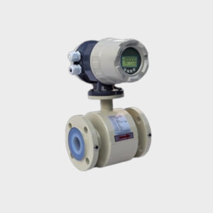
Juice Milk MAG Flow Meter
Principle of Operation
Faraday’s Law The operation of a magnetic flow meter or mag meter
is based upon Faraday’s Law, which states that the voltage induced
across any conductor as it moves at right angles through a magnetic
field is proportional to the velocity of that conductor.
Faraday’s Formula
E is proportional to V x B x D where:
E = The voltage generated in a conductor
V = The velocity of the conductor
B = The magnetic field strength
D = The length of the conductor
Application :
Juice Milk Mag Flow Meter with pulse;4~20mA and RS485 output
Sensor Output:
Pulse;4~20mA;HART;RS485;MODBUS;GPRS
Lining and Body Matereial
PTFE, Rubber Lining and cast
steel; stainless steel body material
- Description
- Reviews (1)
Description
Description
Technical Data
Production Name | MODEL NO- ILUX –EM -03 JUICE MILK MAG FLOW METER |
Medium | Fruit Juice, Milk, Water; Waste water; Mud and various kinds of conductivity liquid |
Diameter | DN10~DN2000mm |
Accuracy | +/-0.5% |
Temperature | <80℃(rubber); <180℃(PTFE) |
Pressure | 10 kg/cm² Max (Higher on Request) |
Flow speed | 0.3~10m/s |
Requirement of pipeline | Upstream ≥5DN;Downstream≤10DN |
Electrode | Stainless steel 316L(standard); Titanium; Tantalum ; Hast alloy |
Lining | PTFE; Rubber |
Connection | Flange; thread; clamp on |
Body material | Cast steel ;stainless steel |
Power supply | 220V;24V;Battery |
Output | Pulse;4~20mA;HART;RS485;MODBUS;GPRS |
Communication | HART;RS485;MODBUS |
Explosion proof | Customized |
Protection | IP65 or IP67 |
Environment | Environment:-20~60℃ |
ITEM |
ELECTRODE SPECIFICATION |
Material |
The Medium |
SS316L |
Water; Waste water; Corrosive water and Mud, etc; |
Hastelloy B |
Non-oxidizing acids at concentrations less than 10%; NAOH Concentrations less than 50% |
Hastelloy C |
Mixed Acid and Oxidizing salts |
Titanium |
Salt and weak acid ;Not application: hydrochloric acid, nitric acid and other reducing acids |
Tantalum |
Hydrochloric acid(<40%); Sulphuric acid and Other oxidizing acids |
Platinum |
Almost all acid-base salt solution But not application for aqua regia, except ammonium salt |
Tungsten carbide |
Pulp ; sewage ;slurry |
FLOW METER LINNING SPECIFICATION
Lining | Name | Symbol | Performance | Temp | Medium | |
Rubber | Neoprene | CR | Normal wear resistance acid salt | <80c | Water |
|
Polyurethane | PU | Good wear resistance , bad corrosive resistance | <80c | Pulp | ||
Fluoroplastic | Teflon | PTFE | Acid Salt with stable Chemical properties |
<140c |
Acid Salt | |
Polyvinyl Fluoride | FEP | Chemical properties same | <180c | Acid Salt |
Flow Meter Installation
1. Installation location
- Avoid the magnetic objects and equipment with strong electromagnetic field;
- should install the flow meter at ventilated location;
- Avoid the location wherer ambient temperature above 50℃ and relative humidity above 90%;
- The water flow meter should be installed at somewhere spacious;
- The 4-20Ma Sensor Electromagnetic Water Flow Meter Smart should be installed behind pump and the value should install at downstream.
Flow Sensor Installation
- Must to ensure the pipeline is filled and without bubbles to keep the high accuracy;
- The flow direction should keep with sign on the body of flow meter;
- Ensure the double electrodes keep Horizontal;
- If the medium is mixed by liquid and solid,Pls install it at vertical to extend the working life of lining;
- If the environment with shocked pls install the bracket at both front and behind;
- If the medium is pollution liquid, should install the flow meter at bypass pipe and don’t interrupted when you on service;
TROUBLESHOOTING
Symptom | Probable Cause | Solution | ||
Measurement is not | 1. Parameter wrong | Check the parameters (Transmitter, |
|
|
accurate | ||||
K factor and size) | ||||
2. Pipe is not fully filled | Check if meter is fully filled | |||
Flow rate indication is | (1) Make sure meter is properly | |||
unstable | grounded to a good earth ground | |||
1. Grounding issue | (2) Please use ground ring when the pipe | |||
is not conductive, such as PVC or other | ||||
plastic pipe | ||||
2. Air | Make sure fluid does not contain |
air |
||
bubbles | ||||
3. Converter location – outside | Make sure Converter is not too close to | |||
electrical interference | sources of electrical interference | |||
No Display | 1. No power | Apply correct power | ||
2. Incorrect power | Check power value | |||
3. Wiring connections | Check power input/output connections | |||
4. Fuse blown | Replace fuse | |||
Operating conditions
Temperature | ||
Process temperature | Hard rubber liner: ‐5…+60°C | |
Polypropylene liner: ‐5…+90°C | ||
PTFE liner: ‐5…+120°C | ||
Ambient temperature | Standard (with aluminum converter housing): | |
(all versions) | ‐20…+60°C (Protect electronics against self‐ | |
heating with ambient temperatures above 55°C) | ||
Storage temperature | ‐20…+70° | |
Pressure | ||
EN 1092‐1 | DN2200…3000: PN 2.5 | |
DN1200…2000: PN 6 | ||
DN200…1000: PN 10 | ||
DN65…150: PN 16 | ||
DN10…50 : PN 40 | ||
Other pressures on request | ||
ISO insertion length | Optional for DN15…600 | |
ASME B16.5 | 1…24″: 150 lb RF | |
Other pressures on request | ||
DN10…1000 / 2…40″: 10 K | ||
Other pressures on request | ||
Pressure drop | Negligible |
Joe Doe –
Awesome!